Designing a 3D model that looks perfect in Autodesk Fusion 360 is only the first step. A professional mechanical design must also be easy to manufacture, inspect, assemble, and modify.
This is where Design for Manufacturing (DFM) becomes important.
DFM is the process of designing parts with manufacturing methods, material limitations, tolerances, tooling, cost, and production requirements in mind. Whether a component will be CNC machined, 3D printed, laser cut, or manufactured using another process, applying DFM principles early can prevent expensive redesigns later.
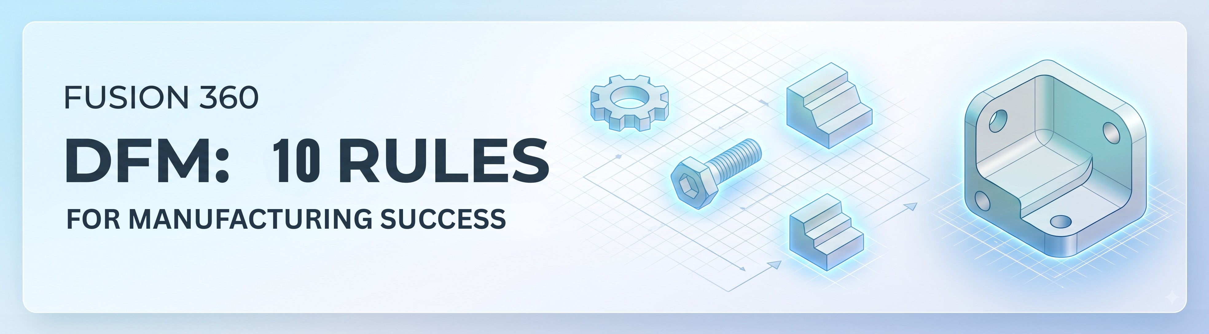
In this guide, we'll explore 10 important DFM rules every Fusion 360 designer should know and explain how you can apply them during the modeling process.
⚙️ What Is Design for Manufacturing (DFM)?
Design for Manufacturing is an engineering approach that considers how a product will actually be manufactured while it is being designed.
A CAD model may be geometrically correct but still be difficult or expensive to manufacture. For example, a part may contain:
- Extremely small holes
- Deep and narrow pockets
- Sharp internal corners
- Unnecessarily tight tolerances
- Difficult-to-machine surfaces
- Excessive material
- Complicated setups
These issues can increase machining time, tooling requirements, material consumption, and production cost. Using DFM principles in Fusion 360 helps designers create models that are not only visually and mechanically correct but also production-ready.
1. Choose the Manufacturing Process First
One of the most important DFM rules is to understand how the part will be manufactured before finalizing the geometry. Different manufacturing processes have distinct limitations.
| Manufacturing Method | Important Design Considerations |
|---|---|
| CNC Machining | Tool access, pocket depth, internal radii |
| 3D Printing | Overhangs, wall thickness, support requirements |
| Sheet Metal | Bend radius, bend allowance, reliefs |
| Injection Molding | Draft angles, wall thickness, parting lines |
| Laser Cutting | Material thickness, kerf, minimum features |
| Casting | Draft, wall thickness, shrinkage |
A geometry that works perfectly for 3D printing may be unnecessarily expensive or impossible to machine using conventional CNC tools.
Machining → Additive Manufacturing → Sheet Metal → Injection Molding → Fabrication
Then create the geometry around the limitations of that process.
2. Avoid Unnecessarily Tight Tolerances
Tolerances are essential in mechanical design, but tighter does not always mean better. For example, specifying Ø20 ±0.01 mm instead of Ø20 ±0.05 mm may significantly increase manufacturing and inspection requirements.
The tighter tolerance may require:
- More precise machines
- Additional finishing operations
- Better inspection equipment
- More production time
- Higher manufacturing cost
3. Design Holes for Standard Tools and Processes
Holes are among the most common features in mechanical components, but their design can strongly affect manufacturability. For CNC-machined parts, avoid creating holes that require unusual or custom tooling unless there is a clear engineering reason.
Whenever possible, use standard drill sizes. For example, instead of designing an unusual Ø7.37 mm hole, consider whether a standard drill size can meet the functional requirement.
Also consider:
- Hole depth & drill access
- Hole diameter & thread type
- Counterbores & countersinks
- Through vs. blind holes
4. Avoid Deep, Narrow Pockets
Deep pockets create serious machining challenges. A CNC tool must reach the bottom of the pocket while maintaining sufficient rigidity.
A very deep and narrow pocket may require long cutting tools, multiple machining operations, reduced cutting speeds, specialized tooling, and additional setups. Long tools can also deflect or vibrate during machining.
- Reduce unnecessary pocket depth
- Increase pocket width
- Use appropriate corner radii
- Design features that allow standard cutting tools
5. Use Appropriate Internal Corner Radii
Sharp internal corners are difficult to machine using conventional milling cutters because round cutting tools naturally create a radius. If you design a perfectly sharp internal corner, a CNC milling operation cannot produce it without specialized processes.
Instead of Sharp internal corner → Difficult to machine, consider Filleted internal corner → Easier to machine.
6. Maintain Practical Wall Thickness
Wall thickness is critical for additive manufacturing, injection molding, casting, and machining. Extremely thin walls can deform, vibrate, break, warp, or increase rejection rates. Excessively thick sections can cause sink marks, internal voids, or wasted material.
7. Minimize Unnecessary Setups
Every additional manufacturing setup increases production time, fixturing costs, and cumulative error. For CNC machining, try to design features that can be cut from as few orientations as possible.
8. Avoid Unnecessary Features
More features do not automatically mean a better design. Every additional pocket, groove, fillet, chamfer, or step increases cycle time and inspection steps. Remove decorative features that serve no functional or structural purpose.
9. Design for Assembly and Inspection
Manufacturing doesn't end when the part comes off the machine. Ensure mating parts have proper clearances, fasteners are reachable with standard tools, and critical datum surfaces are accessible to calipers or CMM probes.
10. Validate the Design Before Manufacturing
Always perform a complete pre-production design review checking geometry, tolerances, manufacturing tool access, assembly clearances, and 2D drawing accuracy.
📋 A Simple DFM Workflow in Fusion 360
⚠️ Common DFM Mistakes in Fusion 360
🚀 Why DFM Matters for Fusion 360 Designers
Fusion 360 provides an end-to-end toolset: parametric modeling, sheet metal, simulation, generative design, and integrated CAM. Top CAD designers don't just ask "Can I model this?" — they ask "Can I manufacture, inspect, assemble, and maintain this?"
Take Your Fusion 360 Skills Further
Want to go beyond basic tools and learn how to design real, manufacturing-ready mechanical assemblies? Build your skills through practical, project-based learning.
 - 3168-360x220.png)
 - 6476-360x220.png)