Designing a complete V6 engine in SOLIDWORKS is one of the best ways to master professional mechanical CAD design. Unlike modeling a single component, this project teaches you how dozens of precisely engineered parts work together to create a fully functional engine assembly.
Whether you're a mechanical engineering student, CAD enthusiast, or design professional, building a V6 engine helps you develop advanced skills in part modeling, assemblies, engineering drawings, and motion studies.
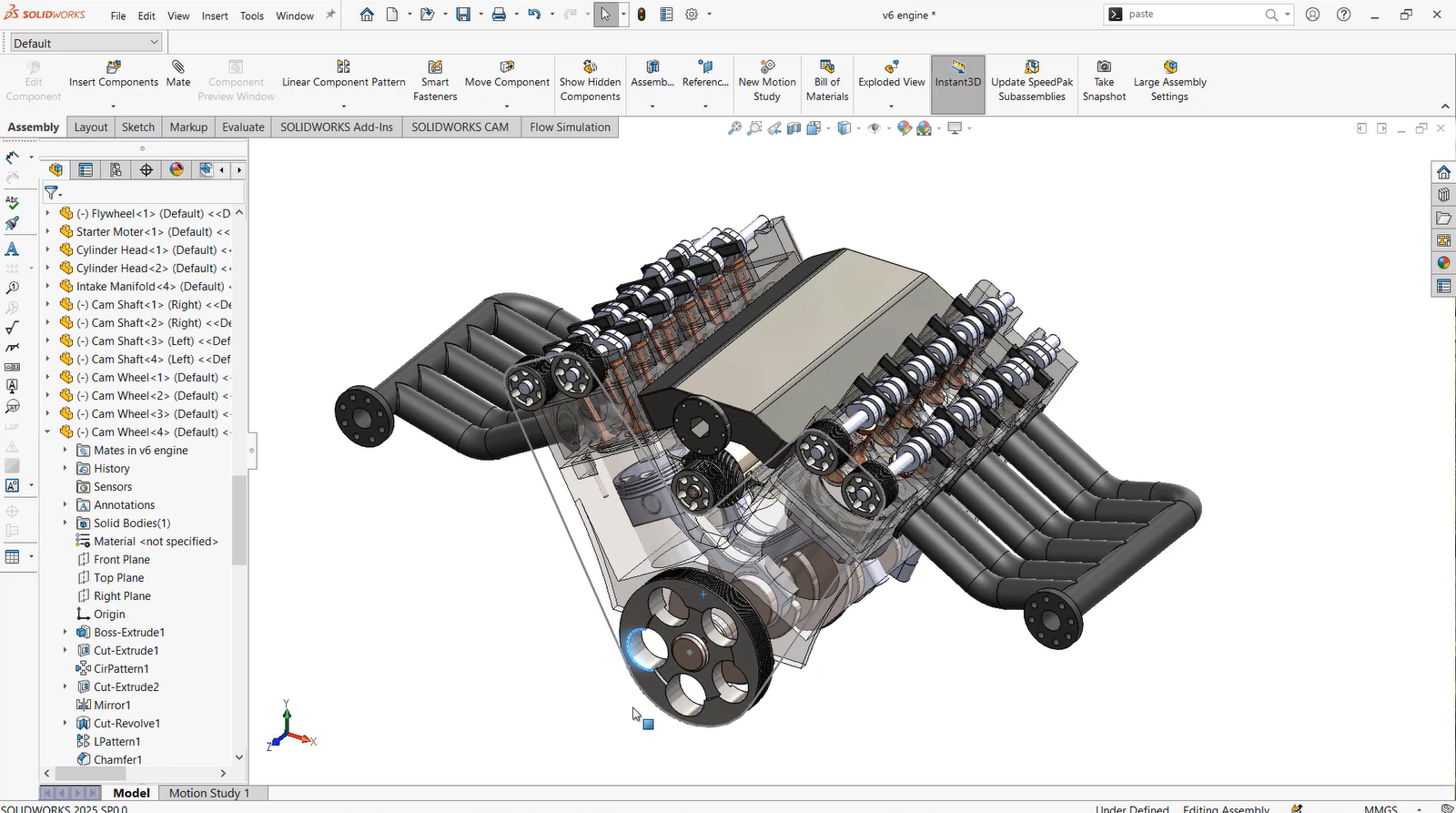
Table of Contents
- Why Design a V6 Engine?
- Understanding Major Components
- Modeling Individual Parts
- Building the Assembly
- Motion Study & Animation
- Engineering Drawings
- Skills You'll Learn
- Common Challenges
- Conclusion
Why Design a Complete V6 Engine in SOLIDWORKS?
Many beginners learn SOLIDWORKS by creating simple brackets, plates, or machine components. While these exercises help develop modeling skills, they don't fully demonstrate how complex mechanical systems are designed.
A complete V6 engine project combines every important workflow used in real-world mechanical engineering:
Instead of understanding isolated features, you'll learn how hundreds of design decisions work together inside one functional mechanical product.
Understanding the Major Components of a V6 Engine
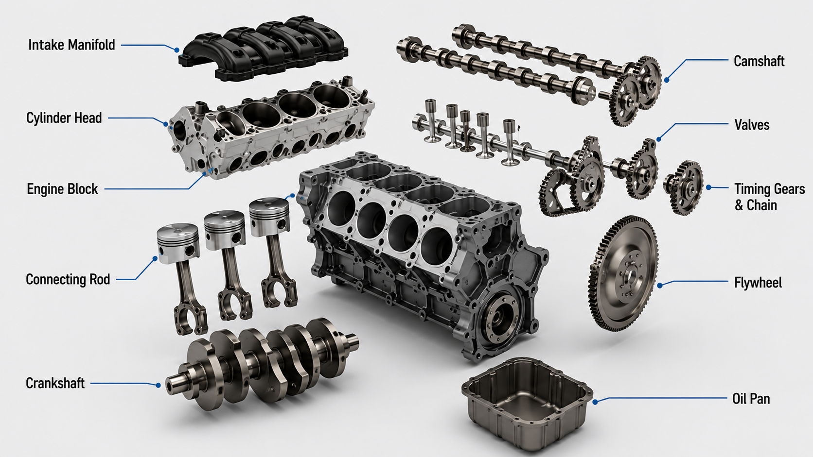
Before opening SOLIDWORKS, it's important to understand what you're actually building. Every component performs a unique function and must fit perfectly inside the complete assembly.
Engine Block
The engine block serves as the structural foundation of the entire engine. It houses the cylinders, supports the crankshaft, and provides mounting locations for numerous engine components.
Key Design Features: Cylinder bores, mounting bosses, oil passages, cooling channels, and main bearing supports.
Crankshaft
The crankshaft converts the pistons' reciprocating motion into rotational motion. It contains multiple crank pins, journals, and counterweights that must be positioned with high precision. Common feature tools include Revolve Boss/Base, Extrude, Fillet, Circular Pattern, and Reference Geometry.
Connecting Rod
The connecting rod transfers force from the piston to the crankshaft. Although it appears simple, its geometry is carefully optimized for strength while minimizing weight.
Piston
A piston contains multiple functional features including the crown, ring grooves, wrist pin hole, and skirt. Proper feature sequencing allows easy modifications later in the design process.
Modeling Individual Components in SOLIDWORKS
Professional engineers rarely design an entire machine in one part file. Instead, every component is modeled separately before being assembled together. This workflow provides clean feature trees, faster rebuild times, and simple design updates.
Typical SOLIDWORKS Features Used:
Professional CAD Practices
- Create fully defined sketches before generating features.
- Use meaningful feature names instead of generic defaults.
- Model every component using clear design intent.
- Avoid unnecessary external references.
- Use equations and dimensions whenever possible.
Building the Complete V6 Engine Assembly
After every component has been modeled, the next step is assembling the engine. This is where individual parts come together to form a fully functional mechanical system using intelligent mating relationships that simulate real-world mechanical constraints.
| Mate Type | Purpose |
|---|---|
| Coincident Mate | Aligns two planar faces perfectly flush. |
| Concentric Mate | Aligns cylindrical features such as shafts, pins, and holes. |
| Distance Mate | Maintains a specified gap or clearance window between components. |
| Parallel / Angle Mate | Keeps selected faces parallel or controls precise rotational orientation. |
| Lock Mate | Restricts all structural degrees of freedom between selected parts. |
Creating an Exploded View & Motion Study
Exploded Views separate every component while maintaining their alignment relationship. For a V6 engine, exploded views clearly demonstrate how the pistons, crankshaft, connecting rods, cylinder heads, camshafts, and timing components stack together for assembly documentation.
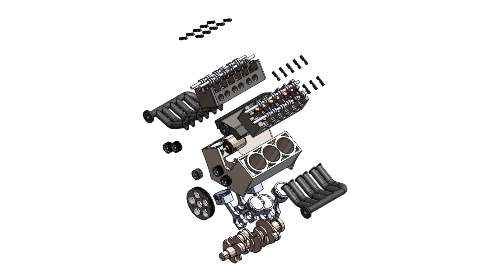
Motion Studies bring the engine to life. Instead of looking at a static mock-up, SOLIDWORKS Motion simulates crankshaft rotation, piston reciprocating travel, connecting rod sway, and synced valve train timing to visually inspect and validate clearances.
Engineering Drawings & Production Outputs
A complete CAD project isn't finished until professional manufacturing drawings have been created. SOLIDWORKS automatically generates drawings directly from the 3D model while maintaining full layout associativity.
- Part & Assembly Sheets: Production drawings complete with section layouts and precise detail views.
- Bill of Materials (BOM): Automated structured lists with precise component mapping, balloon annotations, and customized descriptions.
- GD&T Integration: High-precision tolerance layouts to verify standard industrial machining limits.
Skills You'll Master
Advanced Sketching, Feature-Based Parametric Modeling, Reference Geometries, Large Assembly Management, Sub-assembly Mating, Motion Simulation, Exploded Layout Renderings, and Professional Engineering Drawing Standards.
Common Assembly Challenges
Large mechanical projects introduce unique challenges. Knowing how to handle overdefined sketches, resolving mate conflicts, breaking circular performance references, and managing file rebuild strain is crucial to stable assembly structures. Utilizing smart subassemblies, logical modeling configurations, and proper folder organization saves hours of performance errors.
Build a Complete V6 Engine in SOLIDWORKS
Master professional mechanical design through a complete project-based workflow and gain practical experience with industry-standard SOLIDWORKS techniques.
- Complete Component & Engine Block Modeling
- Large Structural Assembly Management
- Advanced Motion Studies & Interference Analysis
- Professional Associative Production Drawings & BOMs
Frequently Asked Questions
Is this project suitable for beginners?
Yes. However, having basic familiarity with standard sketch constraints, basic extrusion tools, and primary mating constraints will maximize your workflow efficiency.
Will I learn large assembly performance techniques?
Absolutely. The engine setup teaches you complex component nesting, structured mate trees, and performance stabilization frameworks.
Can I add this project to my professional portfolio?
Definitely. A fully functioning, properly constrained V6 engine featuring full motion validation and clean production drawings is an exceptional display of real-world mechanical design skills.
Conclusion
Designing a complete V6 engine in SOLIDWORKS is one of the most comprehensive ways to learn professional mechanical CAD design. It combines advanced part modeling, assembly creation, motion simulation, and engineering documentation into a single real-world project.
Whether you're preparing for a mechanical design career or expanding your CAD portfolio, this project provides practical experience that closely reflects true industrial design engineering workflows.
 - 854-360x220.png)