
 - 5173.png)
Assembly mates define how components fit together and move in a SOLIDWORKS assembly. The right mates can make a model behave like the real mechanism, keep it easy to edit, and help prevent parts from drifting out of position.
This guide covers common mate types, when to use them, and a few habits that make assemblies easier to manage.
What does a mate do?
A mate creates a relationship between two assembly entities, such as faces, edges, planes, axes, or points. Depending on the mate, it can position components, restrict their movement, or allow controlled motion.
For example, a concentric mate can align a shaft with a hole. Add a coincident mate between their ends, and the shaft is positioned axially as well. Together, these relationships describe how the parts fit.
Standard mates
Coincident
A coincident mate places two selected entities together. It is commonly used to align flat faces, edges, or points.
Parallel
A parallel mate keeps two selected entities parallel.
Perpendicular
A perpendicular mate holds two entities at a 90-degree angle.
Tangent
A tangent mate makes two selected surfaces touch at a tangent point or line.
Concentric
A concentric mate aligns the axes of two circular or cylindrical entities.
Distance
A distance mate sets a specified separation between two entities.
Angle
An angle mate sets a specific angle between two entities.
Lock
A lock mate fixes the relative position and orientation of two components.
Mates for controlled movement
Limit distance
A limit distance mate allows movement between minimum and maximum distances.
Limit angle
A limit angle mate allows rotation within a minimum and maximum angle.
Width
A width mate centers a tab, pin, or component between two opposing faces.
Path mate
A path mate makes a point or component follow a selected path.
Mechanical mates
Mechanical mates describe common mechanical relationships directly.
Hinge
A hinge mate allows rotation around an axis while keeping the connected components positioned relative to each other.
Gear
A gear mate relates the rotation of two components. You set the relationship using their sizes or a specified ratio.
Rack and pinion
A rack and pinion mate links the rotation of a pinion to the linear movement of a rack.
Screw
A screw mate links rotation to translation along an axis.
Slot
A slot mate allows a component to move along a slot while keeping it aligned to the slot.
How to choose the right mates
Start with the way the real parts connect. Ask:
- What surfaces or axes define the fit? Use those as your references.
- Which movements should remain? A hinge needs rotation; a slider needs linear travel.
- Which movements should be restricted? Add mates that remove only the unwanted motion.
- Does the mechanism have travel limits? Use limit mates where needed.
- Can you use stable references? Planes, axes, and well-defined features are often easier to maintain than small edges that may change during editing.
A useful approach is to position a component with a small number of clear mates, then check how it moves. Add more only when needed to define the intended behavior.
Common mate problems
Overdefining the assembly
An assembly is overdefined when mates conflict or impose more restrictions than the design allows. This can happen when several mates try to control the same movement.
Unexpected movement
A component may still slide or rotate because its mates do not constrain every degree of freedom.
Parts flipping during mating
SOLIDWORKS may find a valid solution that faces the opposite direction from the one you intended.
Mates that break after edits
Mates attached to small edges or temporary geometry may become unreliable when the model changes.
Final check
After mating an assembly, drag components that should move and confirm that fixed components stay in place. Check the travel range, look for interference, and make sure the mates describe how the mechanism is intended to work.
Well-chosen mates make an assembly easier to understand, update, and review. Start with the real connections between parts, preserve the movement the mechanism needs, and use only the relationships required to define it.
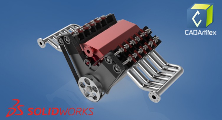
SOLIDWORKS Mechanical Design & Assemblies Masterclass
Master SOLIDWORKS by designing real-world mechanical assemblies from scratch. Build professional engineering projects including a V6 Engine, Differential, Rotary Lobe Pump, Grinder Vise, and Wing Corkscrew while developing industry-ready mechanical design and assembly skills.
Explore the Course → - 6393-360x220.png)
 - 4447-360x220.png)
 - 3972-360x220.png)
