
Introduction
In today's product design and manufacturing industry, 3D CAD (Computer-Aided Design) has become an essential skill for mechanical engineers, product designers, manufacturing professionals, and engineering students. Among all CAD software, SOLIDWORKS is one of the most widely used platforms for designing mechanical components, creating assemblies, validating concepts, and generating production-ready engineering drawings.
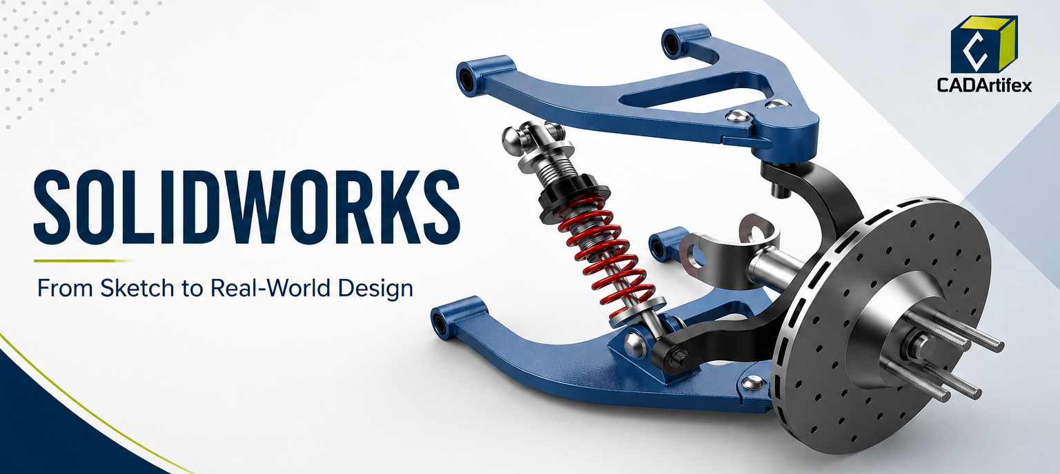
Whether you're designing a simple bracket or a complete automotive suspension system, SOLIDWORKS provides powerful parametric modeling tools that make product development faster, more accurate, and easier to modify.
If you're new to mechanical design, understanding the fundamentals of SOLIDWORKS can open doors to careers in product design, manufacturing, automotive, aerospace, industrial machinery, and consumer products. This guide explains the core concepts every beginner should learn before moving into advanced design projects.
What is SOLIDWORKS?
SOLIDWORKS is a parametric 3D CAD software developed for mechanical design. Instead of drawing static geometry, you create intelligent models driven by dimensions, constraints, and design intent.
Every feature you create is stored inside a FeatureManager Design Tree, allowing you to edit any stage of your design without rebuilding the model from scratch. This parametric workflow makes engineering changes quick while maintaining relationships between sketches, features, assemblies, and drawings.
Understanding the SOLIDWORKS Workflow
Every mechanical design generally follows this three-step sequence:
Step 1: Create a Sketch
Every 3D model starts with a 2D sketch. You'll learn to create:
- Lines & Rectangles
- Circles & Slots
- Splines & Polygons
- Ellipses & Arcs
A properly constrained sketch forms the foundation of an accurate CAD model.
Step 2: Apply Dimensions & Constraints
Sketches should never remain under-defined. Dimensions define size while geometric relations define behavior. Common sketch relations include:
- Horizontal & Vertical
- Parallel & Perpendicular
- Coincident & Tangent
- Concentric, Equal, & Midpoint
Fully defined sketches are easier to edit and reduce modeling errors later.
Step 3: Convert to 3D Parts
SOLIDWORKS converts the 2D sketch into a solid model using features like:
- Extrude & Revolve
- Sweep & Loft
- Rib, Shell, & Draft
- Fillet, Chamfer, & Hole Wizard
These features allow designers to create everything from simple brackets to complex components.
Why Parametric Modeling Matters
Unlike direct modeling software, SOLIDWORKS remembers every modeling step. If a customer changes the length, diameter, thickness, or hole position, you simply edit the sketch dimension, and the entire model updates automatically. This saves enormous engineering time during product revisions.
Reference Geometry
As models become more complex, designers require additional construction geometry. Reference geometry includes:
- Planes
- Axes
- Coordinate Systems
- Points
These references help position sketches, create symmetrical models, and generate advanced features.
Editing Features Efficiently
Professional CAD designers rarely create perfect models on the first attempt. SOLIDWORKS allows you to:
- Edit sketches and modify features
- Reorder operations & roll back the Feature Tree
- Replace dimensions & suppress features
- Rebuild models seamlessly
These tools make engineering changes fast without recreating the model from scratch.
Material Assignment & Mass Properties
Engineering design is not only about geometry; a component must also have physical properties. SOLIDWORKS allows engineers to assign materials such as Aluminum, Steel, Cast Iron, Brass, and Plastic.
Once a material is assigned, the software automatically calculates:
- Mass & Density
- Volume & Surface Area
- Center of Mass
Building Mechanical Assemblies
Individual parts become useful only after assembling them. Assembly modeling combines multiple components into a complete product using mates (e.g., Coincident, Parallel, Concentric, Distance, Angle, Tangent).
Assemblies help engineers:
- Check part fitment
- Detect interference and geometric clashes
- Verify mechanical motion
- Validate overall design intent
Engineering Drawings
Manufacturing teams do not build products from 3D models alone. They require engineering drawings that communicate critical specifications:
- Dimensions & Tolerances
- Section, Detail, and Auxiliary Views
- Center Marks & Notes
- Balloons & Bill of Materials (BOM)
Career Opportunities After Learning SOLIDWORKS
SOLIDWORKS skills are valuable across many industries like Mechanical Design, Product Development, Manufacturing, Automotive, Aerospace, Robotics, and Medical Devices. Common job roles include:
- CAD Designer
- Mechanical Design Engineer
- Product Design Engineer
- Manufacturing Engineer
Common Mistakes Beginners Should Avoid
- Creating under-defined sketches
- Ignoring design intent and using unnecessary features
- Forgetting reference geometry and skipping proper dimensioning
- Creating poor assembly mates or producing incomplete engineering drawings
Final Thoughts
Learning SOLIDWORKS is much more than understanding software commands. It's about developing the engineering mindset needed to create accurate, editable, and manufacturable products. By mastering sketching, parametric modeling, assemblies, and engineering drawings, you'll build the skills required for professional mechanical design careers.
Ready to advance your skills?
The CADArtifex beginner-to-intermediate course follows this progression with 20 structured modules, covering sketching, part modeling, assemblies, engineering drawings, and a complete 20-part suspension system project.
Enroll Now
 - 7074-360x220.png)
 - 3896-360x220.png)
