 - 996.png)
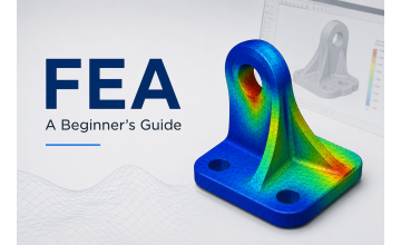
Have you ever run a SOLIDWORKS Simulation study and discovered an unexpectedly high stress concentration in your model? A small region may appear bright red on the stress contour plot, with stress values far higher than the material's yield strength.
Does this mean your component will fail?
Not necessarily. Extremely high stress in Finite Element Analysis (FEA) can indicate a genuine structural problem, a stress concentration, or a mathematical phenomenon known as a stress singularity. Understanding the difference is essential for making reliable engineering decisions.
In this guide, you'll learn why SOLIDWORKS Simulation sometimes reports unrealistic stress values, how to identify stress singularities, and how to determine whether your design requires modification.
What Is Stress in SOLIDWORKS Simulation?
Stress describes the internal forces developed within a material when it is subjected to external loads, such as forces, pressure, torque, or thermal expansion.
SOLIDWORKS Simulation uses the Finite Element Method (FEM) to divide a model into smaller elements, calculate its response to the applied loads and constraints, and display results using contour plots.
For ductile materials under suitable static loading assumptions, engineers often compare the von Mises stress with the material's yield strength. However, interpreting the maximum stress value without examining the model, boundary conditions, and mesh can lead to incorrect conclusions.
What Is a Stress Singularity?
A stress singularity occurs when the idealized mathematical model predicts stress that increases without bound at a particular location.
In an FEA model, this often happens near an idealized point load, a perfectly sharp re-entrant corner, or an abrupt boundary between constrained and unconstrained regions.
As the mesh is refined around the singularity, the calculated peak stress may continue to increase instead of approaching a stable value. This does not automatically mean the entire component is unsafe. It means the local peak stress may not be suitable for direct comparison with the material's yield strength.
Common Causes of Stress Singularities
1. Sharp Internal Corners
Perfectly sharp corners can produce extremely high local stresses, particularly at re-entrant corners where the geometry changes abruptly.
Example: A steel mounting bracket has a sharp internal corner where its vertical wall meets the base. SOLIDWORKS Simulation shows a tiny red region at this intersection.
2. Point Loads Applied to Small Regions
Applying a concentrated force to a single vertex or a very small edge can create a nonphysical stress concentration. Real loads are often transferred through a bolt, bearing, pin, contact surface, or distributed pressure.
3. Fixed Constraints Applied to Small Areas
A fixed restraint prevents all specified translations and rotations at the constrained region. If the real component can rotate, deform, or move slightly, this idealization can produce unrealistic local stresses.
4. Abrupt Changes in Geometry
Sudden transitions in thickness, narrow ligaments, sharp notches, and abrupt changes in cross-section can cause severe stress concentrations. Some idealized geometries can also produce singularities.
Stress Singularity vs. Real Failure: What's the Difference?
A stress concentration and a stress singularity are not the same thing. A stress concentration can represent a real physical increase in stress, while a singularity is an idealized condition in which the calculated local stress does not converge to a finite value.
| Characteristic | Likely Stress Singularity | Likely Physical Stress Concentration |
|---|---|---|
| Peak stress during mesh refinement | Continues increasing | Approaches a stable value when resolved |
| Affected region | Often extremely localized (isolated elements) | May extend over a finite physical region |
| Typical location | Idealized sharp corner, point load, or constraint edge | Fillet, hole, notch, or geometric transition |
| Engineering interpretation | Peak value may not be physically meaningful | Stress can represent a real design condition |
| Next step | Investigate the idealization and assess surrounding field | Evaluate material limits, loading, and failure criteria |
Note: These are diagnostic clues, not absolute rules. A real notch can also create a mathematically singular stress field if its geometry is modeled with an ideal sharp corner.
How to Identify Stress Singularities in SOLIDWORKS Simulation
Follow these steps to investigate an unusually high stress result.
Locate Maximum Stress
- Open completed Simulation study.
- Display von Mises stress plot.
- Identify maximum stress location.
- Zoom into region & check geometry/fixtures.
Determine whether peak occurs at a sharp corner, point load, fixture boundary, or real physical feature.
Refine Mesh Locally
- Edit mesh settings in the study.
- Apply local mesh control around peak area.
- Generate a finer mesh.
- Rerun analysis & compare peak values.
If peak rises substantially while remaining localized, a singularity may exist.
Compare Stress Away from Peak
Inspect stress at several nearby locations or across a consistent section away from the suspected singular point.
If the peak rises but the surrounding stress field remains stable, this strongly indicates a singularity.
Review Loads & Fixtures
Confirm boundary conditions reflect real-world operation:
- Is force on a single vertex?
- Is a large surface unnecessarily fixed?
- Are pin/bolt connectors accurate?
- Are contact conditions verified?
Evaluate Mesh Convergence
Track multiple physical quantities across iterations:
- Displacement at a critical point
- Reaction forces at supports
- Surrounding stress fields
Global response can converge even when local mathematical peak stress does not.
How to Fix Unrealistically High Stress in SOLIDWORKS Simulation
The right solution depends on the physical source of the high stress:
- Fix 1: Model Realistic Geometry – Include actual fillets, chamfers, and radii when they materially affect the stress field. Avoid ideal sharp corners if the manufactured component has a defined radius.
- Fix 2: Improve Load Application – Replace unrealistic point loading with an appropriate distributed load or realistic connection. For bolted or pinned joints, consider suitable connectors and contact definitions.
- Fix 3: Improve Boundary Conditions – Represent supports and connections as realistically as the available information permits. An overly restrictive fixed fixture can create artificial stresses and distort the predicted deformation.
- Fix 4: Use Local Mesh Controls – Refine regions with genuine stress gradients, holes, fillets, and contact zones. Check element quality and confirm that the solution is adequately resolved. A finer mesh does not eliminate a mathematical singularity, so unlimited refinement is not a solution to every high-stress result.
- Fix 5: Validate the Engineering Result – Compare the simulation with analytical calculations, accepted design methods, experimental data, or an appropriate benchmark when available. For ductile materials, consider whether yielding is relevant. For brittle materials, fatigue loading, contact, or buckling, use the appropriate failure assessment rather than relying only on a von Mises peak.
Example: High Stress at a Fixed Bracket Corner
Consider a steel L-bracket subjected to a downward force at its free end. After running a static study, SOLIDWORKS Simulation reports a very high stress at the fixed end of the bracket. How should you interpret it?
Refine the mesh and inspect the stress distribution. If the peak continues increasing while the surrounding results remain stable, the maximum is dominated by a constraint singularity.
Refine the mesh around the feature and check whether the local stress approaches a stable value. If it converges, evaluate the resulting stress against material limits.
This is concerning. Review load values, material specifications, cross-section thickness, and overall stiffness. The design likely requires structural modification.
Common Mistakes to Avoid
- Assuming the maximum von Mises stress always predicts physical failure.
- Refining the mesh repeatedly without investigating the source of the stress.
- Adding arbitrary fillets just to reduce the reported maximum.
- Ignoring unrealistic loads or fixed constraints.
- Treating a converged displacement result as proof that every local stress has converged.
- Comparing results from different mesh sizes without checking equivalent locations and conditions.
- Ignoring fatigue, buckling, contact, or other failure mechanisms when they are relevant.
Conclusion
Extremely high stress in SOLIDWORKS Simulation can indicate a real structural concern, a physical stress concentration, or a mathematical singularity caused by idealized geometry, loading, or boundary conditions.
To distinguish between them, locate the peak stress, refine the mesh, inspect the surrounding stress field, review the model assumptions, and assess convergence using appropriate engineering quantities.
Reliable FEA is not about obtaining a stress plot with fewer red areas. It is about understanding whether the model represents reality and whether the results support a sound engineering decision.
Learn SOLIDWORKS With Practical Mechanical Design Projects
Want to improve your SOLIDWORKS skills, from 3D part modeling and assemblies to professional mechanical design workflows? Explore the complete, project-driven course curriculum.