Learn how to design a real mechanical mechanism in FreeCAD from scratch and bring it to life with motion simulation. This beginner-friendly tutorial covers 3D modeling, assembly, and animation techniques using FreeCAD's powerful tools. Perfect for students, engineers, and CAD enthusiasts looking to improve their design skills.
Most engineers model parts. Smart engineers model parts that prove they work. In this 2-hour live session, we go deep into FreeCAD's Part Design, Assembly workbench, FEM solver, and TechDraw module — together, they turn your 3D model from a pretty picture into a functioning virtual machine with real stress data and shop-ready drawings.
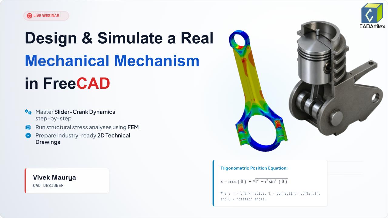
We build the Slider-Crank Mechanism — the beating heart of every internal combustion engine ever made. Sketch it, extrude it, assemble it with kinematic constraints, animate it, stress-test it with CalculiX, and export a blueprint a manufacturer can use. All in one session. All for free.
How continuous rotation becomes reciprocating linear motion — the kinematic equation and real engine physics behind every piston ever built.
Parametric sketches, smart constraints, and Part Design operations — Pad, Pocket, Fillet — applied to real parts: crank disk, connecting rod, piston head.
Cylindrical joints, coincident constraints, and angular drivers that make the mechanism animate on its own — no keyframing, just physics.
Tet-meshing, CalculiX solver, Von Mises stress maps, and safety factor validation — find the failure zone before manufacturing a single part.
ISO fit standards H7/g6, H8/d9, H7/r6 — why they exist, where they go on the drawing, and what happens when they're wrong.
Projection views, GD&T annotations, title blocks — export a production-ready PDF drawing a machinist can read and manufacture from.
Every minute is planned. Here is exactly what gets covered, in order.
Who's in the room, what we're building, and a live look at the finished animated assembly — before we start with a single line of sketch. You'll see the destination before the journey starts.
The Slider-Crank mechanism is inside every car engine, generator, and pump on the planet. We'll decode the one equation — x = r·cos(θ) + √(l² − r²sin²(θ)) — that governs all piston motion, and then prove it by building it live.
A fast, focused tour of the only 4 interface zones you'll touch today. Then the 3 workbenches explained: Sketcher (drafting table), Part Design (workshop), Assembly (factory floor) — and why engineers switch between them for every single part they build.
All three parts built from scratch, live. The crank disk from a constrained sketch padded to 3D. The connecting rod — an I-beam profile chosen for fatigue resistance. The piston with ring grooves, crown depression, and wrist pin bore. Plus: why ISO tolerances H7/g6 and H8/d9 exist and where they go on the drawing.
All three parts come together for the first time. Coincident and Cylindrical constraints lock the crank pin to the connecting rod, and the rod to the piston wrist pin. A Slider joint keeps the piston on its horizontal axis. At the end of this block — drag the crank by hand and the whole mechanism responds.
An angular driver is added to the crank joint. FreeCAD solves the full kinematic chain across 60 frames. The mechanism animates exactly as physics says it must. Then — change the crank offset from 20mm to 35mm and watch the piston stroke increase automatically. Parametric power, live.
The connecting rod gets structural steel properties, a tet-mesh, and a 15,000 N combustion load at the wrist pin. CalculiX solves it. The Von Mises stress heatmap reveals exactly where the part would fail. Safety factor is calculated live. Then — increase the fillet radius and re-run. The stress drops. That's the real engineering loop.
The 3D connecting rod is projected into Front, Top, Right-Side, and Isometric views on an A3 drawing sheet — the international standard 3rd-angle projection. Dimensions are added: rod length, bore diameters, ISO tolerance callout Ø8 H7/g6. Title block filled. Exported as PDF — ready for any machine shop in the world.
Parts exported as STL for 3D printing and STEP for CNC manufacturing. Three real industry examples shown: automotive engine design, robotic linkage systems, and medical prosthetic joints — all validated the same way. Then a preview of the full Mechanics Mastery Course and what's possible when you take today's foundation further.
Open Q&A — any question from "how do I add a second cylinder?" to advanced FEM topics. Community wins celebrated. Complete resource list shared: FreeCAD docs, forum, project file download, and community group. Closed with one thought: every machine in the world started as a parametric sketch. Today you built one.

Vivek Maurya is a CAD Designer and Mechanical Engineering Professional specializing in FreeCAD, 3D modeling, mechanical design, and engineering workflows. With practical experience in CAD development and technical training, he focuses on helping learners understand real-world design processes, simulation concepts, and industry-oriented CAD practices. Through hands-on projects and interactive sessions, he guides students in building strong design skills and applying engineering concepts effectively.
Learn FreeCAD from scratch with this comprehensive online course. Master 3D modeling, assemblies, and 2D drawings using real-world projects, suitable for beginners and professionals.
View FreeCAD Online TrainingNo account needed. Enter your details to save your spot — we'll email you the joining link.

Your information will never be shared with any third party