
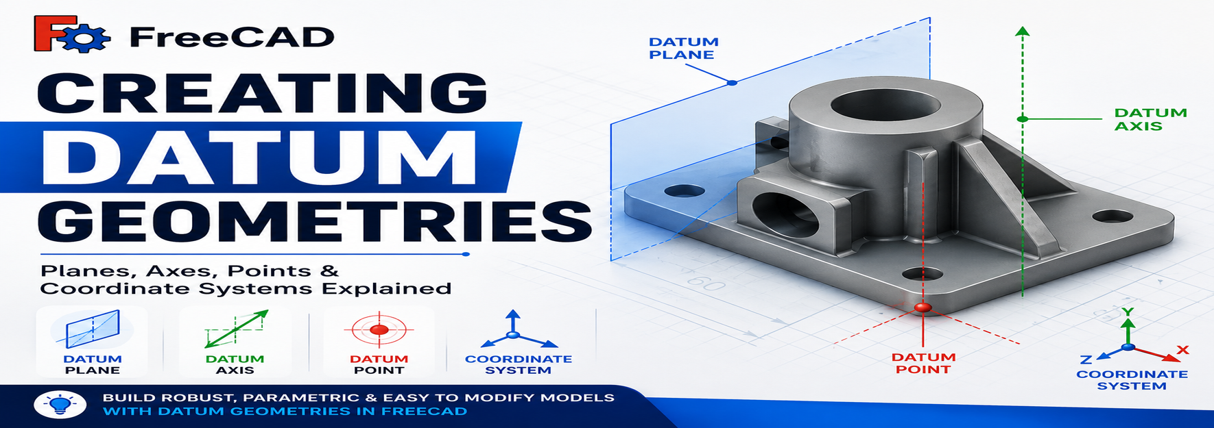
When designing simple parts in FreeCAD, sketches can often be attached directly to existing faces. However, as your models become more complex, relying on model faces can make your designs difficult to modify and maintain.
This is where Datum Geometries become essential. Datum Geometries provide stable reference objects that allow you to build robust, parametric, and easily editable models. Instead of attaching sketches to changing faces, you attach them to independent reference geometry.
In this guide, you'll learn what Datum Geometries are, why they are important, and how to create and use them effectively in FreeCAD.
What Are Datum Geometries?
Datum Geometries are reference elements that help define the position and orientation of sketches, features, and assemblies. They do not add material to your model; instead, they serve as construction references.
The four primary Datum Geometry tools available in the Part Design Workbench are:
- Datum Plane
- Datum Line (Axis)
- Datum Point
- Coordinate System
Why Use Datum Geometries?
Using Datum Geometries offers several parametric design advantages:
- Create sketches away from existing faces
- Build more stable parametric models
- Reduce dependency on changing geometry
- Simplify complex feature creation
- Improve model organization
- Support advanced assemblies and motion studies
Types of Datum Geometries
1. Datum Plane
A Datum Plane is an imaginary construction plane used for creating sketches where no suitable face exists.
Common Uses: Mid-plane sketches, offset sketches, angled sketches, loft profiles, rib creation, and symmetric designs.
2. Datum Axis
A Datum Axis creates a reference line.
Common Uses: Revolve operations, circular patterns, rotational constraints, shaft alignment, and hole positioning.
3. Datum Point
A Datum Point defines a precise location in 3D space.
Common Uses: Hole centers, measurement references, loft guide points, and construction references without relying on existing edges.
4. Coordinate System
A Coordinate System defines a local X, Y, and Z orientation.
Common Uses: Assembly positioning, robot simulations, CNC workflows, exporting parts, and external references.
How to Create a Datum Plane
Creating a Sketch on a Datum Plane
- Select the Datum Plane.
- Click Create Sketch.
- Start sketching normally.
Creating Other Datum Geometries
Datum Axis
Select two vertices, an edge, or a cylindrical face → Click Create Datum Axis → Define attachment → Click OK.
Datum Point
Select a vertex or reference → Choose Datum Point → Set attachment → Click OK.
Coordinate System
Click Create Coordinate System → Attach to a plane or reference → Adjust orientation → Click OK.
Practical Example
Imagine you're designing a gearbox housing and need mounting holes located exactly 25 mm above the base. Instead of sketching on the top face:
- Create an offset Datum Plane.
- Attach a sketch and add mounting holes.
- Modify the offset later if the housing height changes.
The holes automatically update without breaking the model, demonstrating the true power of parametric design.
Best Practices vs. Common Mistakes
✓ Best Practices
- Name Datum features clearly (e.g.,
Plane_Mounting,Axis_Main). - Use Datum Planes instead of temporary construction geometry.
- Avoid attaching sketches directly to model faces.
- Keep Datum Geometries organized in the Model Tree.
- Reuse Datum features instead of creating duplicates.
✗ Common Mistakes
- Sketching Directly on Faces: Downstream sketches fail when editing earlier features.
- Too Many Features: Only create references you actually need.
- Ignoring Naming: Default names like
DatumPlane001become confusing. - Wrong Attachment Mode: Forgetting to verify settings before confirming.
Advantages of Datum Geometries
| Feature | Benefit |
|---|---|
| Datum Plane | Flexible sketch placement |
| Datum Axis | Reliable revolve and pattern references |
| Datum Point | Accurate feature positioning |
| Coordinate System | Better assembly alignment |
| Parametric Design | Easier future modifications |
| Stable References | Reduced model failures |
Frequently Asked Questions
Conclusion
Datum Geometries are among the most powerful tools in FreeCAD for creating robust, parametric, and easily maintainable models. By using Datum Planes, Axes, Points, and Coordinate Systems instead of relying on model faces, you can build designs that are easier to edit, less prone to errors, and better suited for complex engineering projects.
Ready to Master FreeCAD from Scratch?
Take your skills to the next level with hands-on projects, step-by-step lessons, and practical mechanical engineering workflows designed for beginners and intermediate learners.
- ✓ Part & Sketcher Workbenches
- ✓ Parametric Modeling
- ✓ Real-World Assemblies

 - 1050-360x220.png)
 - 28-360x220.png)
