
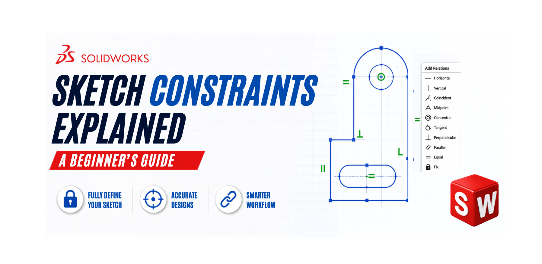
If you are new to SOLIDWORKS, one of the first things you need to understand is sketch constraints. Constraints control how sketch geometry behaves and help you create accurate, predictable, and editable models.
A sketch that looks correct may still be poorly defined if it does not have the right constraints. Learning how to use constraints properly is therefore an essential skill for anyone starting with SOLIDWORKS. In this guide, we’ll explain the most important SOLIDWORKS sketch constraints, how they work, and how to use them effectively.
💡 What Are Sketch Constraints in SOLIDWORKS?
Sketch constraints are relationships that control the position, orientation, size, and behavior of sketch geometry. For example, you can use constraints to tell SOLIDWORKS that:
- Two lines must remain perpendicular.
- A circle must remain concentric with another circle.
- Two lines must always remain parallel.
- Two entities must have equal dimensions.
- A line must remain horizontal.
- Two entities must remain tangent.
🎯 Why Are Sketch Constraints Important?
Imagine creating a rectangular mounting plate. You want the four sides to remain horizontal and vertical, and you want the holes to remain centered. If you simply draw the geometry without constraints, moving one element could easily change the shape.
Constraints prevent this from happening by helping you:
- ✨ Create accurate sketches
- 📐 Maintain design intent
- 🔒 Reduce unwanted movement
- 🎯 Create fully defined sketches
- ⚙️ Make models easier to modify
- 🏗️ Build reliable parametric designs
🧩 Types of Sketch Constraints in SOLIDWORKS
📍 1. Coincident Constraint
Makes two points or entities share the same location (e.g., connecting endpoints for closed profiles in Extruded Boss/Base).
↔️ 2. Horizontal Constraint
Keeps a line or two selected points horizontally aligned. Essential for base lines and reference profiles.
↕️ 3. Vertical Constraint
Keeps geometry vertically aligned. Combined with horizontal constraints, it forms precise rectangular features.
∥ 4. Parallel Constraint
Ensures two selected lines remain parallel across any sketch dimension modifications.
⊥ 5. Perpendicular Constraint
Forces two lines to meet at an exact 90-degree angle for brackets, plates, and frames.
○ 6. Tangent Constraint
Creates a smooth transition between lines, circles, and arcs without sharp corners.
🎯 7. Concentric Constraint
Forces two circles or arcs to share the exact same center point (ideal for shafts, holes, and bushings).
⚖️ 8. Equal Constraint
Locks two or more entities to identical lengths, radii, or diameters automatically.
🪐 9. Symmetric Constraint
Keeps two selected entities symmetric across a specified centerline or reference plane.
◉ 10. Midpoint Constraint
Positions a point or entity relative to the exact center of another entity.
📏 11. Collinear Constraint
Forces multiple straight line segments to lie along the exact same infinite path.
📌 12. Fix Constraint
Locks geometry to its current spatial coordinates. Use sparingly to avoid masking design intent!
📊 Dimensional Constraints vs Geometric Constraints
📐 Geometric Constraints
Define orientation, alignment, and relationships between entities (Horizontal, Vertical, Tangent, Concentric, etc.).
📏 Dimensional Constraints
Define direct numerical magnitudes (Length, Diameter, Radius, Distance, Angle).
Geometric constraints define the relationship. Dimensions define the size. Both work together to fully control a sketch.
🚦 What Is a Fully Defined Sketch?
Some geometry can still move freely. Requires additional constraints or dimensions.
Zero degrees of freedom remain. The geometry is completely stable and controlled.
Conflicting or duplicate constraints applied. Relationships must be simplified to proceed.
🛠️ How to Fully Define a Sketch (Standard Workflow)
- Create basic geometry: Draw lines, circles, and arcs.
- Add geometric relationships: Apply horizontal, vertical, tangent, concentric constraints.
- Add dimensions: Define functional lengths, diameters, and spacing.
- Check sketch status: Verify via the status bar (Under/Fully Defined).
- Resolve conflicts: Remove redundant or over-defining dimensions.
📌 Example: Creating a Simple Mounting Plate
- Step 1 (Rectangle): Draw four lines.
- Step 2 (Constraints): Apply Horizontal to top/bottom, Vertical to sides, Coincident at corners.
- Step 3 (Size): Add overall length and width dimensions.
- Step 4 (Holes): Draw two interior circles.
- Step 5 (Positioning): Apply concentric, midpoint, or linear position dimensions.
- Step 6 (Hole Size): Add diameter dimensions (use Equal constraint if matching).
- Step 7 (Validation): Verify that geometry updates predictably when dimensions are altered.
⚠️ Common SOLIDWORKS Sketch Constraint Problems
- Over-Defined Sketch: Conflicting relationships applied. Solution: Examine warning indicators and delete redundant constraints.
- Over-Reliance on Fix: Masks parametric relationships. Solution: Use dimensions and geometric references instead.
- Missing Dimensions: Profile shape is locked, but scale is unconstrained.
- Incorrect Relationships: Accidental constraints (e.g., parallel instead of perpendicular).
⭐ Best Practices for SOLIDWORKS Sketch Constraints
- 🧠 Think About Design Intent: Anticipate how the component must react during future revisions.
- 🪐 Use Symmetry: Mirror identical geometry across centerlines to minimize dimension clutter.
- 🚫 Avoid Excessive Fix Constraints: Build intelligent parametric links.
- 🎯 Don't Over-Constrain: Apply only the constraints required to achieve stability.
- 🟢 Fully Define Production Sketches: Keep critical features fully constrained.
- 📐 Use Construction Geometry: Lay reference lines for alignment, symmetry, and spacing.
- ⚓ Anchor to the Origin: Prevent the entire sketch from drifting in 3D space.
📋 SOLIDWORKS Sketch Constraints Cheat Sheet
| Constraint | Main Purpose |
|---|---|
| Coincident | Connects points or entities at the exact same location |
| Horizontal | Keeps geometry horizontally aligned |
| Vertical | Keeps geometry vertically aligned |
| Parallel | Keeps two lines equidistant across their length |
| Perpendicular | Forces entities to meet at an exact 90° angle |
| Tangent | Creates a smooth continuous curve-to-line transition |
| Concentric | Aligns center points of circles, arcs, or cylinders |
| Equal | Maintains identical size, length, or radius |
| Symmetric | Mirrors geometry across a central reference line |
| Midpoint | Locks an entity to the precise halfway point of a line |
| Collinear | Aligns multiple lines along a single continuous vector |
| Fix | Freezes entities at their current coordinates |
📝 Final Thoughts
Understanding SOLIDWORKS sketch constraints is one of the most important steps in becoming proficient with CAD modeling. Instead of simply drawing geometry that looks correct, constraints allow you to create sketches that behave predictably when dimensions are modified.
Start with the fundamentals—Coincident, Horizontal, Vertical, Parallel, Perpendicular, Tangent, Concentric, Equal, and Symmetric—and gradually combine them with dimensional constraints to build clean, professional parametric models.
🚀 Ready to take your SOLIDWORKS skills further?
Explore the SOLIDWORKS Mastery Pack by CADArtifex to master part modeling, assemblies, sheet metal, and mechanical design through structured, practical training.
Explore the SOLIDWORKS Mastery Pack 🎓
 - 7074-360x220.png)
 - 3896-360x220.png)
