
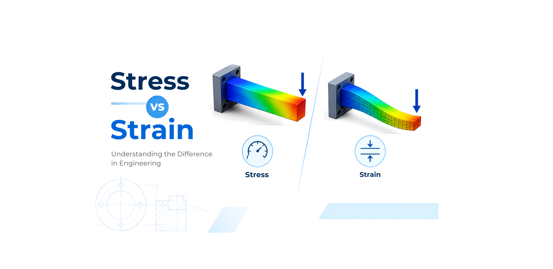
When a mechanical component is subjected to a force, it experiences internal resistance and may change its shape or size. Two fundamental concepts used to describe this behavior are stress and strain.
Although these terms are closely related, they describe two different aspects of how a material responds to an applied load. Understanding the difference between stress and strain is essential for mechanical design, structural analysis, and Finite Element Analysis (FEA).
What Is Stress?
Stress is the internal resistance developed within a material when an external force is applied. In simple terms, stress tells us how much internal force is distributed over a given area of a material.
Where:
- σ = Stress
- F = Applied force
- A = Cross-sectional area
The SI unit of stress is Pascal (Pa), which is equal to one Newton per square meter (N/m²). In engineering applications, MPa (Megapascal) is commonly used.
Consider a metal rod with a cross-sectional area of 100 mm² subjected to a tensile force of 10,000 N.
σ = 10,000 / 100
σ = 100 N/mm² = 100 MPa
Therefore, the rod experiences a tensile stress of 100 MPa.
Types of Stress
Stress can occur in several forms depending on how the load is applied:
1. Tensile Stress
Tensile stress occurs when a component is being pulled apart.
- Tension in a bolt
- A cable carrying a suspended load
- A metal rod being stretched
2. Compressive Stress
Compressive stress occurs when a component is being pushed or squeezed.
- Columns supporting a structure
- A compressed spring
- A machine component under compressive loading
3. Shear Stress
Shear stress occurs when forces act parallel to a surface, causing adjacent layers of material to slide relative to each other.
- A bolt subjected to a transverse load
- Riveted joints
- Cutting operations
4. Bending Stress
Bending loads can produce both tensile and compressive stresses within a component. For example, when a beam bends, one side may experience tension while the opposite side experiences compression.
5. Torsional Stress
Torsional stress develops when a component is subjected to a twisting moment or torque. Shafts, drive axles, and transmission components commonly experience torsional stress.
What Is Strain?
Strain describes the amount of deformation a material undergoes when subjected to an applied load. While stress describes the internal force condition, strain describes the resulting change in dimensions or shape.
Where:
- ε = Strain
- ΔL = Change in length
- L0 = Original length
Strain is dimensionless because it is a ratio of two lengths. It may also be expressed as a percentage.
Suppose a 100 mm long rod stretches by 0.2 mm.
ε = 0.2 / 100 = 0.002
As a percentage: 0.002 × 100 = 0.2%
Therefore, the rod experiences a strain of 0.002 or 0.2%.
Types of Strain
- Tensile Strain: Occurs when a material increases in length due to a tensile load.
- Compressive Strain: Occurs when a material decreases in length due to compression.
- Shear Strain: Represents deformation caused by shear loading and describes the change in angle between material planes.
- Volumetric Strain: Describes the change in volume relative to its original volume.
Stress vs Strain: Key Difference
• Stress = Internal force per unit area
• Strain = Deformation relative to original dimension
| Feature | Stress | Strain |
|---|---|---|
| Meaning | Internal force developed in a material | Deformation caused by loading |
| Formula | σ = F / A | ε = ΔL / L0 |
| SI Unit | Pascal (Pa) | Dimensionless |
| Common Engineering Unit | MPa | mm/mm or % |
| Describes | Internal loading | Material deformation |
| Directly Measurable? | Usually calculated from load and area | Measured/calculated from deformation |
| Main Purpose | Evaluate material loading | Evaluate material deformation |
Relationship Between Stress and Strain
Stress and strain are strongly related in the elastic region of a material's behavior. For a material behaving elastically:
Hooke’s Law for linear elastic behavior
Here, E is the Young’s Modulus, which represents the stiffness of a material. A material with a higher Young’s Modulus generally requires more stress to produce the same amount of elastic strain.
For example, steel has a much higher Young’s Modulus than many plastics. This means that, under comparable loading conditions, a steel component generally undergoes less elastic deformation than a plastic component.
Understanding the Stress-Strain Curve
A stress-strain curve is one of the most useful ways to understand how a material behaves under loading. A typical tensile curve can be divided into several important regions:
- Elastic Region: The material returns approximately to its original shape after the load is removed.
- Yield Point: Marks the beginning of significant plastic deformation in many materials.
- Plastic Region: Removing the load does not completely restore the original shape.
- Ultimate Tensile Strength: The maximum engineering stress reached during a tensile test.
- Fracture: Eventually, the specimen undergoes localized deformation and breaks.
Note: The exact shape depends on the material and testing conditions. Not every material exhibits a clearly defined yield point.
Why Stress and Strain Matter in CAD and FEA
Stress and strain are especially important when designing mechanical components. In Finite Element Analysis (FEA), engineers simulate how a component behaves under different loading conditions to examine:
- Equivalent stress (von Mises)
- Principal stress
- Shear stress
- Strain & Displacement
- Factor of Safety (FoS)
For example, in a bracket supporting a heavy load, an FEA study helps identify where stress concentrations occur and how much the bracket deflects. This informs design improvements like modifying geometry, increasing wall thickness, adding fillets, or selecting higher-strength materials.
Stress Concentration and Strain
Sharp corners, holes, notches, keyways, and abrupt geometry changes cause stress concentrations. Adding an appropriate fillet smooths load paths, reduces local peak stresses, and improves fatigue life—showing why these concepts are vital even during initial CAD modeling.
A Simple Way to Remember
- The force acting on the band creates stress within the material.
- The stretch you see represents strain.
Stress = What the material experiences internally • Strain = How much it deforms.
Conclusion
Stress and strain are two fundamental concepts in mechanical engineering and material science. Stress describes the internal force per unit area generated within a material, while strain describes the resulting deformation relative to the material’s original dimensions. Understanding both concepts helps engineers evaluate whether a component can withstand an applied load, how much it may deform, and whether its design is suitable for the intended application.
- ✅ Practical, Project-Based Learning
- ✅ Beginner to Advanced Concepts
- ✅ Industry-Focused Workflows
- ✅ Lifetime Access
 - 1185-360x220.png)
 - 8434-360x220.png)
 - 1452-360x220.png)
